 |
Component-based development (CBD)
and object-oriented development go hand-in-hand, and it
is generally recognized that object technology is the
preferred foundation from which to build components. I
typically use
UML
2 component diagrams as an
architecture-level artifact, either to model the
business software architecture, the technical software
architecture, or more often than not both of these
architectural aspects. Physical architecture
issues, in particular hardware issues, are better
addressed via
UML deployment diagrams or
network diagrams. In fact I'll often iterate
back and forth between these diagrams. |
|
Component diagrams are particularly
useful with larger teams. Your
initial architectural
modeling efforts during
cycle 0 should focus on identifying the initial
architectural landscape for your system. UML component
diagrams are great for doing this as they enable you to
model the high-level software components, and more
importantly the interfaces to those components. Once
the interfaces are defined, and agreed to by your team,
it makes it much easier to organize the development
effort between subteams. You will discover the need to
evolve the interfaces to reflect new requirements or
changes to your design as your project progresses,
changes that need to be negotiated between the subteams
and then implemented appropriately.
Figure 1
presents an example component model, using the UML 2
notation, for the university system.
Figure 2 depicts the same
diagram using UML 1.x notation. As you can see, there
are several notational differences. UML 2 components
are modeled as simple rectangles, whereas in UML 1.x
there were depicted as rectangles with two smaller
rectangles jutting out from the left-hand side. As you
can see UML 2 uses this symbol as a visual stereotype
within the rectangle to indicate that the rectangle
represents a component although the textual stereotype
of component is also acceptable (as you see with
the Schedule component). Both diagrams model
dependencies, either between components or between
components and interfaces. You can also see that both
diagrams use the lollipop symbol to indicate an
implemented interface although the UML 2 version
introduces the socket symbol to indicate a required
interface. As far as I’m concerned the socket symbol is
effectively a visual stereotype applied to a dependency,
the equivalent textual stereotype is shown on the
dependency between the Persistence component and
the JDBC interface.
Figure 1. UML 2.x component
diagram.

Figure 2. UML 1.x component
diagram.

Diagrams such as
Figure 1 are often referred to as “wiring diagrams”
because they show how the various software components
are “wired together” to build your overall application.
The lines between components are often referred to as connectors,
the implication being that some sort of messaging will
occur across the connectors.
I usually draw component diagrams
on whiteboards although for both of the examples I’ve
used a drawing tool to depict the notation accurately.
You can use component diagrams for both logical and
physical modeling although I prefer to use them for
physical modeling of the software architecture of a
system. Figure 1 shows the
large-scale domain components for the system we’re
building, including two user interface components which
map to two different applications which we’re building
as part of the overall system. This diagram includes
both business and technical architecture aspects – the
components with the infrastructure and
database stereotypes are clearly technical in nature
– and that’s perfectly fine. The important thing is
that we’re considering both business and technical
aspects in our architecture, not just technical issues,
and for whatever reason we’ve chosen to create a single
diagram which includes both views.
Components may both provide and
require interfaces. An interface is the definition of a
collection of one or more methods, and zero or more
attributes, ideally one that defines a cohesive set of
behaviors. A provided interface is modeled using the
lollipop notation and a required interface is modeled
using the socket notation. A port is a feature of a
classifier that specifies a distinct interaction point
between the classifier and its environment. Ports are
depicted as small squares on the sides of classifiers.
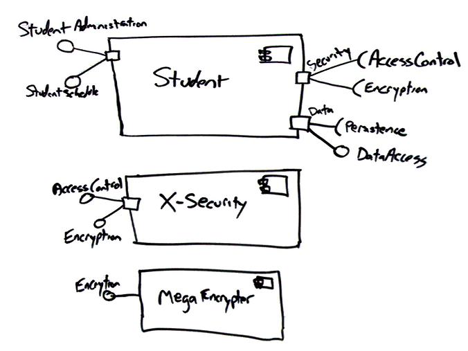
For example,
Figure 3 shows
a detailed component diagram which contains three
components. There are several interesting features to
note about this diagram:
-
Ports can be named, such as the
Security and Data ports on the
Student component.
-
Ports can support unidirectional
communication or bi-directional communication. The
Student component implements three ports, two
unidirectional ports and one bi-directional ports.
The left-most port is an input port, the Security
port is an output port, and the Data port is a
bi-directional port.
-
The StudentAdministration
and StudentSchedule interfaces are application
specific and may include overlapping method
signatures. I’ve found this approach to be more
understandable to the clients of the component as each
application team is provided their own specific
interface which isn’t encumbered with methods they
don’t need.
-
The diagram isn’t “wired”
together yet – I haven’t connected the Student
component to the two security components yet.
-
You don’t need to use all of the
provided interfaces of a component. My team has
decided to use the X-Security component for
access control and the MegaEncrypter
component for encryption. Both of these fictional
components are commercial off the shelf packages
(COTS) which we’ve purchased. Although X-Security
implements both security interfaces required by
Student the other component implements the
Encryption interface much more efficiently so
we’ve decided to use both security components.
Figure 3.
Modeling interfaces and ports.
So how do you actually build a
component? Although there are various strategies to do
so, there are several basic principles that you can
follow. Figure 4
depicts a design for the Student component, depicting it
as a UML frame. It’s also common to use "composite
structure", e.g. a rectangle with the component stereotype
in the top-right corner, instead of a frame because a
component really is a structure composed of smaller
elements. Whether you call it a frame, a composite
structure, or something else, the diagram is pretty much
the same.
Interesting points about this diagram are:
-
I simplified the ports to either
provide or require a single interface. This enables
me to easily and explicitly model the relationships
between the ports and the internals of the component.
-
I’ve modeled relationships
between ports and internal classes in three different
ways: as a stereotyped delegates relationship, as a
delegates relationship, and as a realizes
relationship. A delegates relationship is a line
with an open arrowhead on it and a realizes
relationship is a dashed arrow with a closed
arrowhead. Because the delegates notation is
exactly the same notation that is used for
unidirectional associations there is an opportunity
for confusion – as a result I recommend indicating the
stereotype on the relationship to make it clear what
you mean. The realizes notation, for example
AdministrationFacade realizes the port containing
the StudentAdministration interface, used to be
my preferred approach because in my mind ports are
logical modeling constructs that are realized by
physical constructs such as classes. However, the
delegates association has the advantage that it
indicates the flow of communication and as a result
seems to be easier to understand.
-
The Data and Security
classes use the same names as the corresponding ports.
-
Classes such as
AdministrationFacade, ScheduleFacade,
StudentData, Data, and Security
implement the Façade design pattern (Gamma et. al.
1995). The basic idea is that they implement the
public operations required by the interfaces,
operations that typically just delegate messages to
the appropriate classes. Together the
AdministrationFacade, ScheduleFacade, and
StudentData classes implement the public
interface of the Student component.
StudentData, Data, and Security wrap
access to external components so that the internal
classes are not directly coupled to other physical
components.
-
Expect to adapt incoming/outgoing interactions back
and forth between data-oriented and object-oriented
messages. An incoming message may be implemented as a
web service which takes XML as a parameter and returns
XML as the result. The internal objects within the
component, on the other hand, need messages sent to
them with either objects or data as parameters and
return values. The implication is that you need to
marshal the data and objects back and forth between
each other, something addressed by the Adapter
design pattern (Gamma et al., 1995).
-
Another way to implement the
public interface would have been to implement a single
façade class called StudentComponent which
implements the required public interfaces and
delegates appropriately.
-
When designing the StudentData
class the team realized that it needed to work with
our existing XMLProcessor component, therefore
we added the connection to this component.
Figure 4.
Designing a component.
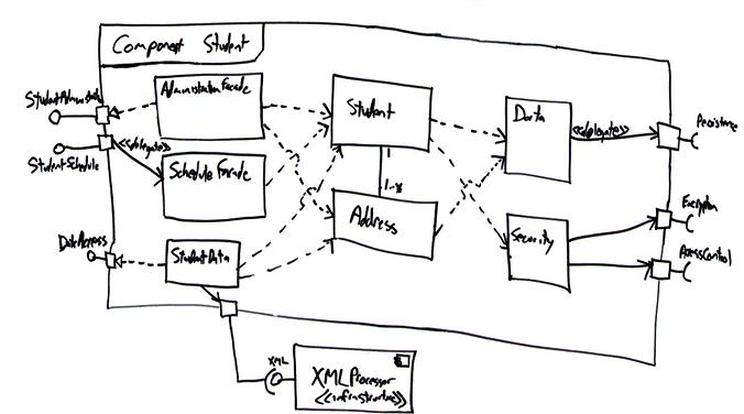
Figure 3 makes
it obvious that building components is costly. Creating
the Student component as shown in
Figure 3
doesn’t make much sense – I’ve added five new classes to
support two domain classes, a clear case of
overbuilding. This approach would make sense if there
was twenty classes, and would make a lot of sense for
fifty domain classes, because the additional five
classes reduce the coupling within your system while at
the same time implement a large-scale, reusable domain
component. The point is that you should only take a
component-based approach when the benefit of doing so
outweighs the additional cost.
Creating Component Diagrams
There are two fundamental
strategies for developing a component model, either top
down or bottom up. Given the choice I prefer the
top-down approach because it provides a good mechanism
for identifying the “software landscape” early in the
project, something that is particularly important for
teams comprised of several subteams because you want to
work towards the same vision. Unfortunately a top-down
approach suffers from the tendency to promote
over-architecting, and hence over-building, of your
system. For example Figure 1
calls out Security and Persistence
components but you might not yet need anything even
remotely that complicated. It would be a serious
mistake to focus on building these two components
instead of implementing actual business functionality
that your stakeholders actually need.
A second way to develop component
models is from the bottom up. I’ll do this when we have
an existing collection of classes that have been
developed and we decide to componentize our design.
Componentizing is often done to rescue reusable
functionality out of an existing application or to split
an application up so it can be easily dispersed between
subteams. When I’m componentizing an existing object
design I’ll often iterate through the following steps:
-
Keep components cohesive.
A component should implement a single, related set of
functionality. This may be the user interface logic
for a single user application, business classes
comprising a large-scale domain concept, or technical
classes representing a common infrastructure concept.
-
Assign user interface classes
to application components. User interface
classes, those that implement screens, pages, or
reports, as well as those that implement “glue logic”
such as identifying which screen/page/… to display
should be placed in components with the application
stereotype. In Java these types of classes would
include Java Server Pages (JSPs), servlets, and screen
classes implemented via user interface class libraries
such as Swing.
-
Assign technical classes to
infrastructure components. Technical classes,
such as those that implement system-level services
such as security, persistence, or middleware should be
assigned to components which have the
infrastructure stereotype.
-
Define class contracts. A
class contract is any method that directly responds to
a message sent from other objects. For example, the
contracts of the Seminar class likely include
operations such as enrollStudent() and
dropStudent(). For the purpose of identifying
components, you can ignore all the operations that
aren’t class contracts because they don’t contribute
to communication between objects distributed in
different components.
-
Assign hierarchies to the same
component. 99.9% of the time I find that it makes
sense to assign all of the classes of a hierarchy,
either an inheritance hierarchy or a composition
hierarchy, to the same component.
-
Identify domain components.
A domain component is a set of classes that
collaborate among themselves to support a cohesive set
of contracts. The basic idea is that classes, and even
other domain components, are able to send messages to
domain components either to request information or to
request an action be performed. On the outside, domain
components appear simple, actually they appear like
any other type of object but, on the inside, they are
often quite complex because they encapsulate the
behavior of several classes. A key goal is you want
to organize your design into several components in
such a way as to reduce the amount of information
flowing between them. Any information passed between
components, either in the form of messages or the
objects that are returned as the result of a message
send, represents potential traffic on your network (if
the components are deployed to different nodes).
Because you want to minimize network traffic to reduce
the response time of your application, you want to
design your domain components in such a way that most
of the information flow occurs within the components
and not between them.
-
Identify the “collaboration
type” of business classes. To determine which
domain component a business class belongs to you need
to analyze the collaborations it is involved with to
determine its distribution type. A server class is one
that receives messages, but doesn’t send them. A
client class is one that sends messages, but doesn’t
receive them. A client/server class is one that both
sends and receives messages. Once you have identified
the distribution type of each class, you are in a
position to start identifying potential domain
components.
-
Server classes belong in their
own component. Pure server classes belong in a
domain component and often form their own domain
components because they are the “last stop” for
message flow within an application.
-
Merge a component into its
only client. If you have a domain component that
is a server to only one other domain component, you
may decide to combine the two components.
-
Pure client classes don’t
belong in domain components. Client classes don’t
belong in a domain component because they only
generate messages, they don’t receive them, whereas
the purpose of a domain component is to respond to
messages. Therefore, client classes have nothing to
add to the functionality offered by a domain component
and very likely belong in an application component
instead.
-
Highly coupled classes belong
in the same component. When two classes
collaborate frequently, this is an indication they
should be in the same domain component to reduce the
network traffic between the two classes. This is
especially true when that interaction involves large
objects, either passed as parameters or received as
return values. By including them in the same domain
component you reduce the potential network traffic
between them. The basic idea is that highly coupled
classes belong together.
-
Minimize the size of the
message flow between components. Client/server
classes belong in a domain component, but there
may be a choice as to which domain component they
belong to. This is where you need to consider issues
such as the information flow going into and out of the
class. Communication within a component will often be
simple message sends between objects in memory,
communication between components may require an
expensive marshalling effort in which a message and
its parameters are converted to data, transmitted, and
then converted back into a message again.
-
Define component contracts.
Each component will offer services to its clients,
each such service is a component contract.
Table 1
summarizes several design principles presented in Agile
Software Development (Martin, Newkirk, Koss 2003) for
improving the quality of packages or components. I
present them here because I find them of greatest value
when it comes to component modeling.
Table 1. Component design
principles.
|
Principle |
Description |
|
Acyclic Dependencies |
Allow no cycles in the
dependencies graph between components. For example
disallow A è
B è C
è A
because it includes a cycle. |
|
Common Closure |
The classes of a component
should be closed together against the same kinds of
changes. A change that affects a class within a
component should not affect classes outside that
component. In other words your components should be
cohesive in that sweeping changes across several
components are not required. |
|
Common Reuse |
The classes in a component are
reused together. If you reuse one class in a
component you reuse them all. This is another
principle addressing cohesion. |
|
Dependency Inversion |
Abstractions should not depend
on details, instead details should depend on
abstractions. |
|
Open-Closed |
Software elements should be
open for extension but closed for modification. |
|
Release-Reuse Equivalency |
The granule of reuse is the
granule of release. In other words you should not
reuse only part of a released software element. |
|
Stable Abstractions |
A component should be as
abstract as it is stable. A component should be
sufficiently abstract so that it can be extended
without affecting its stability. |
|
Stable Dependencies |
Depend on the direction of
stability – If component A depends on component B,
then B should be more stable (e.g. less likely to
change) than A. |
Remaining Agile
My most successful use of component
models was with a team where we drew a diagram similar
to, albeit a much larger one with over
twenty components, on a whiteboard. This whiteboard was
situated in the team work area where everyone could see
the board. We developed the diagram early in the
project and updated it as required throughout the
project. We kept it on the board because it provided a
high-level map of the architecture of our software, a
map that we used from time to time as we worked and more
importantly engendered many interesting conversations
regarding the overall system design.
There are several advantages to
components that promote agility. First, components are
reusable building blocks from which you can build
software, increasing your productivity as a developer.
Second, components can improve your testing productivity
because they can be treated as elements which you can
black-box unit and integration test. Testing is
discussed in detail in
Full Lifecycle Object-Oriented Testing (FLOOT).
This artifact description is excerpted from Chapter 10 of
The Object Primer 3rd Edition: Agile Model Driven
Development with UML 2.
 |
|
The Object Primer 3rd Edition: Agile Model Driven
Development with UML 2 is an
important reference book for agile modelers,
describing how to develop 35
types of agile
models including all 13
UML 2 diagrams.
Furthermore, this book describes the techniques
of the
Full Lifecycle Object Oriented Testing
(FLOOT) methodology to give you the fundamental
testing skills which you require to succeed at
agile software development. The book also
shows how to move from your agile models to
source code (Java examples are provided) as well
as how to succeed at implementation techniques
such as
refactoring and
test-driven development
(TDD). The Object Primer also includes a
chapter overviewing the critical database
development techniques (database refactoring,
object/relational mapping,
legacy analysis, and
database access coding) from my award-winning
Agile Database Techniques
book. |
 |
|
Agile Modeling: Effective Practices for Extreme
Programming and the Unified Process is the seminal
book describing how agile software developers approach
modeling and
documentation. It describes principles and
practices which you can tailor into your existing
software process, such as
XP, the
Rational Unified Process (RUP), or the
Agile Unified Process (AUP), to streamline your
modeling and documentation efforts. Modeling and
documentation are important aspects of any software
project, including agile projects, and this book
describes in detail how to
elicit requirements,
architect, and then
design your system in an agile manner. |
 |
|
The Elements of UML 2.0 Style describes a collection
of standards, conventions, and
guidelines
for creating effective
UML diagrams. They are based on sound, proven
software engineering principles that lead to diagrams
that are easier to understand and work with. These
conventions exist as a collection of simple, concise
guidelines that if applied consistently, represent an
important first step in increasing your productivity as
a modeler. This book is oriented towards
intermediate to advanced UML modelers, although there
are numerous examples throughout the book it would not
be a good way to learn the UML (instead, consider
The Object Primer). The book is a brief 188
pages long and is conveniently pocket-sized so it's easy
to carry around. |
Translations
I actively work with clients around the world to
improve their information technology (IT) practices as
both a mentor/coach and trainer. A full
description of what I do, and how to contact me, can be
found here.
The notation used in these
diagrams, particularly the hand
drawn ones, may not conform
perfectly to the current version
of the UML for one or more of
reasons:
- The notation may have
evolved from when I
originally developed the
diagrams. The UML
evolves over time, and I may
not have kept the diagrams
up to date.
- I may have gotten it
wrong in the first place.
Although these diagrams were
thoroughly reviewed for the
book, and have been reviewed
by thousands of people
online since then, an error
may have gotten past of us.
We're only human.
- I may have chosen to
apply the notation in
"non-standard" ways.
An agile modeler is more
interested in created models
which communicate
effectively than in
conforming to notation rules
set by a committee.
- It likely doesn't matter
anyway, because the
modeling tool(s) that
you're using likely won't
fully support the current
version of the UML notation
perfectly anyway.
Bottom line is that you're
going to be constrained by
your tools anyway.
If you're really concerned
about the nuances of "official"
UML notation then read the
current version of the
UML specification.
|